Motion Sensor
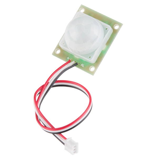
The motion sensor included in your Photon kit uses passive infrared (PIR) light to detect movement in the surrounding environment up to about 10 feet away.

How to Connect Motion Sensor
The motion sensor has a 3-wire JST connector with 3 pins for plugging into a breadboard. (If the end of your connector doesn't have 3 metal pins, attach the JST right angle connector included in your kit.)
To connect a motion sensor to your Photon using the breadboard, you will need:
Motion sensor (with 3-pin JST right angle connector)
3 jumper wires (use different colors to help identify them; it may help to match the sensor wires)
Motion Sensor
Photon Pin
Black - Data
any I/O pin
White - Ground
GND
Red - Power (5-12V)
5V through VIN or V-USB
5V REQUIRED: The motion sensor requires 5V of power to operate.
If your Photon is being powered through the barrel jack, connect to the VIN pin.
If your Photon is being powered through the Micro-USB port, connect to the V-USB pin.
Here are the steps to connect the motion sensor to your Photon using the breadboard:
Insert the 3 pins of the motion sensor connector into different terminal strip rows on the breadboard. (Different terminal strip rows have different row numbers.)
Plug one end of a jumper wire into the same terminal strip row as the sensor's black wire. Plug the other end of this jumper wire into an I/O pin on the Photon circuit board.
Plug one end of a second jumper wire into the same terminal strip row as the sensor's white wire. Plug the other end of this jumper wire into a pin hole connected to GND: either plug it into a negative power rail (which is connected to GND via a different jumper wire), or plug it directly into a GND pin on the Photon circuit board.
Plug one end of a third jumper wire into the same terminal strip row as the sensor's red wire. Plug the other end of this jumper wire into either the VIN pin or V-USB pin on the Photon circuit board (or to a positive power rail on the breadboard that is connected to VIN or V-USB). If your Photon is being powered through the barrel jack, connect to the VIN pin. Otherwise, if your Photon is being powered through the Micro-USB port, connect to the V-USB pin.
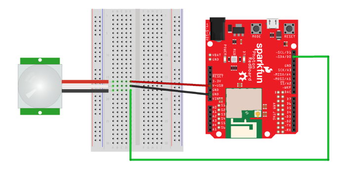
Here's a wiring diagram showing a possible way to connect a motion sensor:

Keep in mind that your connection can look different than this example diagram:
Your motion sensor pins could be inserted into different row numbers. (The example connects the sensor pins to rows 16-18 on the left side of the breadboard.)
Your motion sensor pins could be inserted into a different column of the breadboard. (The example connects the sensor pins into column A of the terminal strip rows.)
Your sensor's black wire could connect (through a jumper wire) to a different I/O pin. (The example connects to the D0 pin.)
Your sensor's white wire could connect (through a jumper wire) to either to a different GND pin or to a negative power rail connected to a GND pin. (There are three available GND pins.)
Your sensor's red wire could connect (through a jumper wire) to either the VIN pin or V-USB pin (or to a positive power rail that's connected to one of these pins). (The example connects directly to the V-USB pin.)
How to Code Motion Sensor
The basic steps to use a motion sensor in your app code are:
Declare a global variable to store the I/O pin number for the motion sensor.
Set the pin mode for the motion sensor pin in the
setup()function.Use a
digitalRead()statement to check whether the sensor detects any motion, and add code statements that should be performed if motion is detected (or not detected).
Global Variable
You should declare a global variable to store the I/O pin number that the motion sensor's data wire is connected to. This will make it easier to understand your code (and easier to modify the code if you were to connect the motion sensor to a different pin number).
Add this code statement (modify if necessary) before the setup() function:
This line of code does 3 things (in order):
It declares a data type for the variable's value. In this case,
intstands for integer (whole number). Photon pin numbers are always treated asintvalues (even though they have letters).It declares the variable's name. In this example, the variable will be called
motion. You can change the variable name, but choose a name that will make sense to anyone reading the code.It assigns a value to the variable. In this example, the variable's value will be equal to
D0. If necessary, modify this value to match the actual I/O pin number that your button is connected to.
Set Pin Mode
You need to set the pin mode for the motion sensor to be used as an input.
Add this code statement (modify if necessary) within the setup() function:
The pinMode() method requires two parameters inside its parentheses (in this order):
The I/O pin number, which can be the actual pin number (such as:
D0, etc.) or a variable that stores a pin number. In this example, a variable namedmotionis listed. If necessary, change this to match the variable name for your button.The mode value, which will always be
INPUT_PULLUPfor a motion sensor.
Check If Motion Detected
The digitalRead() method is used to check whether the sensor currently detects any motion.
Add this code (modify as necessary) to your app within the loop() function or a custom function:
In the first code statement, a local variable named motionState is declared that will have a data type of int (integer). This variable is made equal to whatever value is returned by the digitalRead() method. You can change the name of this variable, but it will make sense if it's similar to the variable name used for the motion sensor pin number.
The digitalRead() method requires one parameter insides its parentheses:
The I/O pin number, which can be the actual pin number (such as:
D0, etc.) or a variable that stores a pin number. In this example, the variable namedmotionis listed. If necessary, change this to match the variable name for your motion sensor's pin number.
The digitalRead() method will return a value of either HIGH or LOW (which are treated as if they were int values):
HIGHindicates that motion is NOT currently detected.LOWindicates that motion is currently detected.
The condition listed inside the parentheses of the if statement checks whether the value of motionState is equivalent to LOW:
If this condition is true, the code within the curly braces of the
ifstatement will be performed. You will need to add code statements within the curly braces that perform the actions you want.If this condition is false (because the
motionStateisHIGH), the code within the curly braces will NOT be performed. Optionally, you can add an else statement to perform a different set of code statements when motion is not detected.
IMPORTANT: You will notice that a delay() of 2 seconds is included when motion is detected. This delay is needed to allow the motion sensor to capture a new "snapshot" of the environment before checking the sensor again.