A-1 Circuit Board
GOAL: Understand the features of your Photon circuit board (pins, ports, buttons, LED lights)
TASK: Review the information below as you examine the circuit board in your Photon kit, and answer the questions in this document.
Circuit Board
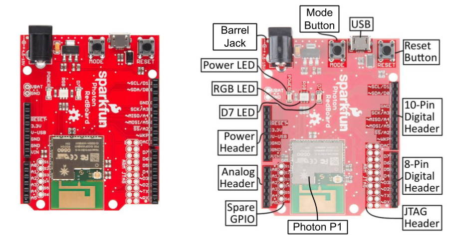
The SparkFun Photon kit contains a printed circuit board (PCB) that incorporates the Particle Photon P1 microcontroller, which will act like the “brain” of your IoT device. This circuit board also has various pins, ports, buttons, and LED lights. SparkFun refers to this circuit board as the Photon RedBoard (because of its color).
You can connect various inputs (such as: sensors, buttons, etc.) and outputs (such as: motors, lights, etc.) to the pins on the circuit board to create a device. Then you can control your device by programming an app that will run on the Photon microcontroller.
SparkFun Photon RedBoard
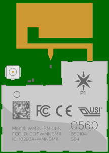
Photon P1 Microcontroller
Input/Output Pins
Power Supply Ports and Pins
Buttons
LED Lights

Photon Microcontroller
A microcontroller is a small computer on a single integrated circuit that contains a processor (CPU), memory, storage, and programmable input/output pins. The Photon microcontroller also has an integrated Wi-Fi chip and antenna, which makes it great for IoT devices.
Photon P1 Tech Specs
CPU: 32-bit 120Mhz ARM Cortex M3
Memory: 128KB RAM
Storage: 1MB Flash
Wi-Fi: 2.4GHz 802.11b/g/n

Compared to the tech specs of a "regular" computer, a microcontroller is much less powerful – it has a slower processor, less memory, and less storage. This is because microcontrollers are used in devices that have dedicated functions (such as: automobile engine control systems, medical devices, office machines, appliances, etc.). These dedicated devices typically don’t require as much computing power.
Firmware and Device App
A microcontroller is controlled by its firmware, which acts as its operating system. Periodically, your Photon will need to update its firmware. If this is necessary, the firmware update will occur automatically when you download a new app to your Photon over Wi-Fi.
A microcontroller is designed to store only one app, which will run automatically. If you need to change your Photon device's app, the new app has to be downloaded over Wi-Fi (and will replace the old app). You will have to code the apps for your Photon – though you'll get some practice and help to do so.
Particle Cloud
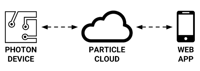
When the Photon is powered on, it will automatically try to connect to Wi-Fi (using a programmed list of Wi-Fi network logins). Once the Photon is connected to Wi-Fi, it will automatically try to connect to Particle Cloud, which is a cloud service that Particle provides for all of its microcontroller devices. All of the Photon's internet communications are routed through Particle Cloud.
Particle Cloud can be used to:
Code and store all your different Photon device apps (using online Particle Build code editor)
Update the app stored on your Photon device
Update the firmware on your Photon device
Send and receive data between your Photon device app and your web app
Manage your Photon device remotely

Input/Output Pins
The Photon circuit board has numerous I/O pins used to connect various inputs (such as: sensors, buttons, etc.) and outputs (such as: motors, lights, etc.). These I/O pins have small plugs that allow you to easily connect (and disconnect) the wires for inputs and outputs.
Digital Pins
The circuit board has a set of digital pins labeled as: D0, D1, D2, D3, D4, D5, D6, D7. Digital pins are used to connect inputs or outputs that use binary values (such as: HIGH or LOW, etc.). For example:
Digital Input: A motion sensor detects either "motion" or "no motion."
Digital Output: A LED light can be set to be "on" or "off."
Analog Pins
The circuit board has a set of analog pins labeled as: A0, A1, A2, A3, A4, A5. Analog pins are used to connect inputs or outputs that use a range of values (such as: 0-255, etc.) For example:
Analog Input: A photocell can detect a range of values based on the amount of light measured.
Analog Output: A speaker can produce a range of tones that have different frequencies.
TWIN PINS: Analog pins A2, A3, A4, and A5 are each represented by two pins on the Photon board. The duplicate pins are labeled as: SS/A2, SCK/A3, MISO/A4, MOSI/A5.
If you use one of these pins, you should not use its twin. For example, you could connect a part to either A2 or SS/A2 (choose only one), but you could not connect two different parts to these twin pins at the same time.
Analog Output Using PWM
Any analog pin can be used for analog inputs. However, only certain pins can be used for analog outputs. (Confusingly, some of the pins capable of analog output are labeled as digital pins.)
The Photon uses pulse-width modulation (PWM) to make a digital output signal (which has only two values: HIGH or LOW) act like an analog output signal (which has a range of values). Certain outputs (such as: speaker, servo motor, etc.) require a connection to an I/O pin capable of PWM.
These Photon pins can be used as analog outputs using PWM: A4, A5, D0, D1, D2, D3, RX, TX, WKP.
Special Pins
The circuit board also has I/O pins with "special" labels. Most of these "special" pins are used to connect with parts that require specific data communication protocols:
SPI Pins: SS/A2, SCK/A3, MISO/A4, MOSI/A5
SPI stands for "Serial Peripheral Interface"
For example, a Micro OLED display would be connected using the SPI pins.
I2C Pins: SDA/D0, SCL/D1
I2C stands for "Inter-Integrated Circuit"
For example, an accelerometer would be connected using the I2C pins.
UART Pins: RX, TX
UART stands for "Universal Asynchronous Receiver-Transmitter"
For example, a fingerprint scanner would be connected using the UART pins.
However, any of these "special" pins can also be used as "regular" I/O pins.
Power Supply Ports and Pins
The Photon circuit board must receive power from an external power source (such as: USB, battery, or outlet). The Photon circuit board will then supply power to any connected inputs and outputs.
Power Supply Ports
The Photon circuit board can receive power through either one of its power supply ports:
Barrel Jack: A barrel jack adapter can be plugged in to provide power from an external supply such as a battery, outlet, etc.
Micro-USB: A Micro-USB cable can be plugged in to provide power from a computer's USB port, USB charger, etc.
POWER ON/OFF: The Photon circuit board does not have an "on/off" switch. As soon as a power source is connected to the USB port or barrel jack, the Photon will power on and start running. To turn off the Photon, you have to disconnect its power source.
Power Supply Pins
The Photon circuit board can supply power to connected inputs and outputs through these pins:
POSITIVE PINS
I/O Pins: These pins can supply 3.3 volts (by reducing the incoming voltage from the USB or barrel jack power source). Certain inputs and outputs (but not all) get their power from an I/O pin.
3.3V: This pin supplies 3.3 volts (by reducing the incoming voltage from the USB or barrel jack power source).
V-USB: If a power source is connected to the Micro-USB port, this pin supplies ~5 volts.
VIN: If an external power supply is connected to the barrel jack, this pin supplies the same voltage as the external supply (which could range from 4.5-15 volts). For example, if a 9V battery adapter were plugged into the barrel jack, this pin would supply 9 volts. If a USB adapter were plugged into the barrel jack, this pin would supply ~5 volts.
NEGATIVE PINS
GND: This pin acts as the ground (negative terminal) when powering inputs and outputs. The Photon circuit board has 3 available GND pins.
A breadboard can be used to connect multiple inputs and outputs to the same power supply pins. Section 1.3 of this tutorial will explain how this works.
Buttons
The Photon circuit board has two built-in buttons used for special purposes:
Mode: This button is used to switch your Photon between different modes such as: Connected, Listening, Safe, and Device Firmware Upgrade. Normally, you will not need to use this button.
Reset: This button can be used to restart your Photon – forcing it to reconnect to the internet and restart its device app. Occasionally, you might use this button to restart your app.
LED Lights
The Photon circuit board has three built-in LED lights:
Power: This red LED indicates the Photon is receiving power (from the barrel jack or USB). If this LED is off, then no power source is connected (or the Photon device is damaged).
RGB: This LED changes its color and activity pattern to indicate the current mode and connection status of the Photon device.
D7: This blue LED is connected to the D7 pin and can be controlled by your Photon device app, which can be helpful for testing purposes.
Normal RGB Patterns
Whenever you connect a power source to the Photon (or restart it using the Reset button), the Photon should power on, connect to Wi-Fi, connect to Particle Cloud, and start running its device app.
During this startup process, the RGB color will change from green to cyan (light blue) and the RGB activity will change from "blinking" (fast blinking) to "breathing" (slow blinking).
Whenever the device app or firmware on the Photon is updated, the RGB will blink pink during the download and installation. Once the update is complete, the Photon will automatically restart itself.
RGB Color
RGB Activity
Photon Device Status
Green
Blinking
Trying to connect with Wi-Fi
Cyan (light blue)
Blinking
Connected to Wi-Fi + Trying to connect with Particle Cloud
Cyan (light blue)
Breathing
Connected to Wi-Fi and Particle Cloud (device app running)
Pink
Blinking
Receiving new device app or new firmware over Wi-Fi
Other RGB Patterns
If your Photon device displays one of these other RGB patterns, then the Photon has encountered an issue or has been placed into a different mode. Consult your teacher to troubleshoot your device.
RGB Color
RGB Activity
Photon Device Status
Green
Breathing
Connected to Wi-Fi – but could not connect to Particle Cloud
Blue (dark blue)
Breathing
Could not connect to Wi-Fi
Blue (dark blue)
Blinking
Listening Mode (ready to add new Wi-Fi login)
Pink
Breathing
Safe Mode (does not run device app)
White
Breathing
Device's Wi-Fi module has been turned off
Orange-Yellow
Blinking
DFU Mode (ready for manual device firmware upgrade)
Red
Blinking
Firmware crash error
More Info
The SparkFun Photon RedBoard Hookup Guide provides more details about this circuit board.